Due Date:Fri 15 December Sun 17 December 2023, before 23:59 (Blackboard's clock).
Team Size: 2 (pair design/programming)! Note that as of the 2017-2018 Academic Year, each International student should team up with "local"
(i.e., whose Bachelor degree was obtained at the University of Antwerp).
Assignment overview:
Solve exercises
Solve assignment, iteratively:
Implement Statechart wrt. requirements
Generate Python code from the Statechart
Test your solution
Solution should pass given scenarios
Implement one extra test sceneario
Write report
Submitting your solution:
Only one member of each team submits a full solution. This must be a ZIP-archive that includes:
Your report (HTML or PDF)
All the files needed to run your solution, including the files from the "starting point" that you were not allowed to edit, and your generated Python code
The other team member must submit a single (plain text or HTML) file containing only the names of both team members. This will allow us to put in grades for both team members in BlackBoard.
The goal of this assignment is to familiarize yourself with Statechart modeling, simulation, testing and code generation. We will use itemis CREATE (formerly called "YAKINDU Statechart Tools").
Getting Started
Note: On the university PCs, itemis CREATE is pre-installed and ready-to-use.
Clone the StartingPoint git repository into your itemis CREATE workspace, and import it as a project (without copying the files).
Exercises
Before you start working on this assignment, you must solve 5 small exercises. Each exercise shows you a small Statechart model, and asks a question about its behavior. You should include the answers to the exercises in your report.
The exercises can be found in the StartingPoint git repository. In the `exercises' directory, you'll find 5 files (A.ysc, B.ysc, ...). Each of them is a Statechart model that you should open in itemis CREATE. Each model includes a question (in a 'comment' element). You must answer this question, and include your answer in your report.
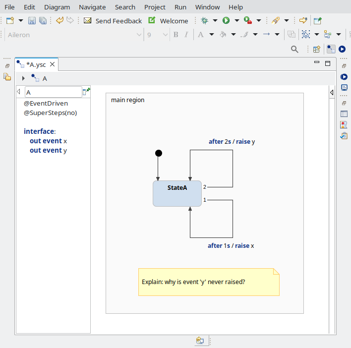
Example: one of the exercises
Feel free to run the models in itemis CREATE.
There also exists a test script (exercises_test.py) that runs all of the examples with a fixed sequence of input events, and checks if the expected output events occur. To run this script, you must first generate Python code: in itemis right-click on PythonGenerator.sgen, Generate Code Artifacts). Also have a look at the source code of the script. You will test your solution to the assignment in a similar fashion.
To solve the exercises, you must have a good understanding of the precise semantics of itemis CREATE.
The semantics are as follows:
The execution of a Statechart is a sequence of Run-To-Completion (RTC) steps
An RTC-step can only triggered by:
An input event
A timer that elapses (actually, an elapsing timer generates an input event behind the scenes)
An RTC-step is instanteneous: it takes zero time.
In between RTC-steps, the Statechart is idle (it will not change its state), and time may pass.
An RTC-step consists of one or more fair-steps:
During the first fair-step, only the input event that triggered the RTC-step is active.
During a fair-step, orthogonal regions are visited left-to-right, or top-to-bottom:
Within one fair step, every (orthogonal / non-overlapping) region is allowed to fire at most one transition. A region will fire a transition only if it has an enabled transition (wrt. the currently active event, and the transition's guard condition).
When a transition fires: first, all the exit actions of all the exited states are executed (in order: child to parent), then the action of the transition itself, followed by the enter actions of the entered states (in order: parent to child)
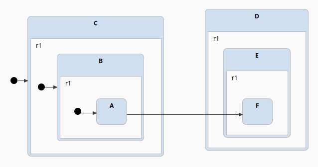
In this example, when firing the transition from A to F, first the exit actions of A, B, and C are executed, then the actions of the transition itself, and finally the enter actions of D, E and F (in that order).
Any internal events that are raised (as a result of firing transitions), are added to the internal event (FIFO) queue.
When a fair-step has completed:
if the internal event (FIFO) queue is not empty, then a new fair-step starts. The next event is popped from the queue, and it becomes the new active event.
if the internal event queue is empty, then no more fair-steps are executed, and the RTC-step ends.
Example:
Consider the following Statechart in the figure below.
After initialization, the current states are: OrthogonalState, A, C, E.
Then, the Statechart remains idle until it receives an input event. Suppose at time T=5s, the input event e is received. This triggers the execution of an RTC step.
The RTC step starts with a fair-step, where regions r1, r2 and r3 (in that order) are allowed to fire at most one transition each.
Only r1 has an enabled transition (because event e is active), so only r1 fires.
During the firing of that transition, the internal event f is raised, an appended to the internal event queue.
The fair-step ends, and one more fair-step is executed, because the internal event queue is not empty.
So again, r1, r2 and r3 are allowed to fire at most one transition.
This time, the regions r2 and r3 will fire, because event f is active.
The second fair-step ends, and since the internal event queue is empty, the RTC step also ends.
Even though all transitions fired in a certain order, all of it happened at the same point in (simulated) time.
Now, the Statechart will again remain idle until another input event occurs.
Time
r1
r2
r3
=0
Initialization
enter A
enter C
enter E
>0 && <5s
Idle
=5s
RTC step (input=e)
Fair-step (event=e)
fire (exit A, raise f, enter B)
Fair-step (event=f)
fire (exit C, enter D)
fire (exit E, enter F)
=5s
End of RTC step
Please remember that these precise semantics are specific to itemis CREATE. Other Statechart tools (e.g., STATEMATE, Rhapsody, StateFlow) have different semantics.
Attention!
Once you've completed the exercises, you'll probably understand that if you ensure that your transitions always have an event trigger or after-trigger, you have much more control over when your transition will fire, resulting in a solution that is more likely correct and understandable.
Therefore, ensure that every transition always has either an event trigger, or an after-trigger. Never use the following triggers:
after 0 s (can give strange behavior)
after 1 ms (unless of course you really want to wait 1ms)
always
every X s
(no trigger)
Instead, you should probably use an internal event, or the choice-element. Every time you violate this rule, 5% will be subtracted from your grade on this assignment.
Introduction to Assignment
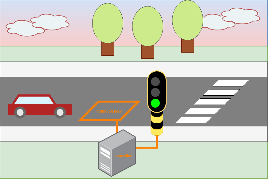
We will use the Statecharts formalism to model the software controller of a "smart" traffic light. The traffic light detects car traffic via an induction loop, and will extend the period where the light is green, if there is traffic.
Artistic impression of our system under study
Controller Interface
The interface between the controller and its environment is fixed: you are not allowed to change it. It consists of the following set of input and output events:
Input event
Received when...
buttonPressed
indicates that the TOGGLE MODE button is pressed down
buttonReleased
indicates that the TOGGLE MODE button is released
carDetected
indicates that a car was detected (via the inductive loop)
Output event
Effect
setLED(boolean)
Controls the status LED (true = on, false = off)
setRed(boolean)
Controls the red light (true = on, false = off)
setYellow(boolean)
Controls the yellow light (true = on, false = off)
setGreen(boolean)
Controls the green light (true = on, false = off)
Controller Requirements
Initially, when the controller starts, the traffic light is set to red, and is in "dumb mode".
In "dumb mode", the traffic light cycles through red, green, yellow and then red again. The light will be red for 2 seconds, green for 2 seconds, and yellow for 1 second.
Note: These time durations are not realistic, but they make it easier to (interactively) test your solution.
The light can be switched from "dumb mode" to "smart mode" (and back) by pressing the TOGGLE MODE-button, and releasing the button quickly (pressed down for strictly less than 2 seconds).
In "smart mode", the behavior is identical to "dumb mode", except that when the light is green, and a car is detected, the light will not turn yellow until 2 seconds have passed since the car-detection-event. For instance, if the light has been green for 1.1 seconds, and a car is detected, then the light will stay green for a total duration of 3.1 seconds.
Even in "smart mode", there is still a limit on how far the green period can be extended: the total green light duration must never be greater than 5 seconds.
There is a status LED that must be on if and only if "smart mode" is activated.
Switching between "dumb mode" and "smart mode" must be seamless: the light should not be reset (e.g., to red). The only difference between these modes is whether new car-detection-events are responded to or not. For instance:
if the light is in "dumb mode", and has been red for 0.2 seconds, and then switches to "smart mode", it should remain red for the remaining 1.8 seconds.
going from "dumb mode" to "smart mode", the traffic light simply starts responding to car-detection-events, possibly extending the current green period (up to a maximum of 5 seconds, even if the switch from "dumb" to "smart" happened at some point during those 5 seconds)
going from "smart mode" to "dumb mode", the traffic light simply stops responding to car-detection events. If the current green period was already extended (due to car-detection-events before switching to "dumb mode"), then the green period remains extended.
Pressing and holding the TOGGLE MODE-button for at least 2 seconds, and then releasing it, starts or ends a "police interrupt". A police interrupt completely overrides the functionality of the traffic light. A police interrupt shows a blinking yellow light. When a police interrupt starts, the yellow light turns on immediately, and stays on for 500 milliseconds, and then off for 500 milliseconds, then on again, etc.
During a "police interrupt", "smart mode" can still be turned on or off in the usual manner (and the status LED should turn on and off accordingly). Of course, the chosen mode has no impact on the traffic light's behavior during a police interrupt.
When a "police interrupt" ends, the traffic light is reset to a red light (for safety reasons), and resumes normal behavior ("dumb" or "smart", depending on the active mode).
Testing your solution
There are three ways you can test your solution:
Use itemis' debugger. This allows you to see your model execute in real-time. You can observe which states are active, and which transitions are being made. You can manually raise input events and observe raised output events.
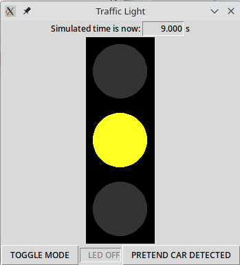
Generate code and run the GUI (trafficlight_gui.py). Here you can see how your model interacts with the `real' system. Input and output events are logged to terminal. You cannot see which states are active, or transitions are made. Upon exiting, a complete trace of all input/output events that occured, will be printed to the terminal.
Screenshot of the GUI. At the bottom of the window, you see the TOGGLE MODE button and the status LED. The PRETEND CAR DETECTED button will trigger a carDetected input event.
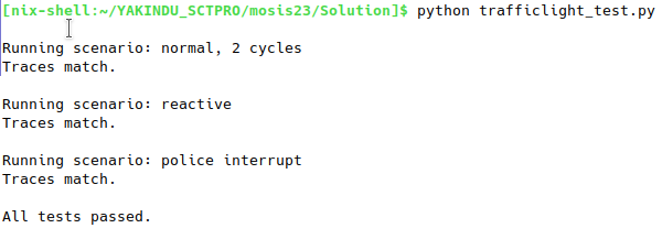
Generate code and run the test script (trafficlight_test.py).
This script will run (the generated code from) your model, but in a non-interactive manner (as opposed to the GUI), and as-fast-as-possible (as opposed to the GUI, which runs in real-time).
The test script contains 3 hard-coded test scenarios, which you are not allowed to alter, and which your model must pass.
Each scenario specifies a sequence of (timed) input events, which the test runner will give to your model as inputs, and an "expected" sequence of (timed) output events, which it expects from your model.
A test scenario passes if the model's "actual" sequence of output events matches the expected sequence.
Note: The actual and expected sequences of output events do not have to match exactly.
For instance, raising the output event setRed(False) three times in a row has the same effect as raising it once (because of idempotence).
Behind the scenes, both sequences are pre-processed to a canonical form, where duplicated events are removed, and therefore ignored by the comparison algorithm.
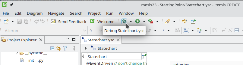
Screenshot of test runner
Further, you must add one extra scenario to this file. This scenario should test a requirement that is not yet covered by the existing tests. Please do not blindly copy an input/output trace that was generated by the GUI. If you do use the GUI to generate a trace, read it, and add comments to it that explain what goes on (similar to the existing scenarios).
Overview of different testing approaches
itemis debugger
Python GUI
Python test runner
white box (e.g., can see what are the current states?)
yes
no
no
interactive or automated?
interactive (real-time)
interactive (real-time)
automated (as-fast-as-possible)
returns
nothing
execution trace
pass or fail (+diff)
Report
You are also required to write a small (HTML or PDF) report.
At the beginning, you list the following things:
The names and student IDs of the team members
The amount of time spent working on the project: Please be honest, this helps us estimate the workload for future assignments.
Your answers to the exercises (A to E).
Then, in a structure you are free to choose, describe:
Your workflow: How did you work together? (pair programming / divided the work / ...) In what order did you implement different features? Encountered any difficulties?
An overview of your final solution (but please do not describe every tiny detail!)
Also explain the extra test scenario you added: why this scenario, what requirements does it cover, ...
Include screenshots where appropriate: A picture is worth a thousand words!
Tips
What is expected
The assignment has been designed specifically to encourage use of as many Statechart features as possible:
composite states
orthogonal states
timed transitions
guard conditions
transition actions
enter/exit actions
internal variables
internal events
(history)
Make sure you understand these features, and use them, where you think they are appropriate.
To give you an indication of the complexity, my own solution consists of 11 states (not counting "regions") and 13 transitions.
Anti-pattern: implementing your own "timer" (don't do this!)
Every year, I see some students implementing some variation of the following:
instead of just creating a transition from A to B labeled after 2s. This serves no purpose whatsoever. It is unnecessarily complex, and the generated code will be less performant. Don't do this!
Resources
Project files from the tutorial: TutorialMicrowaveExamples.zip