|
Research
|
|
|
Research
|
|
This project is for the development of a logisim(version 2.6.1)-verilog translator. Planning:
Report
First Meeting: How to make the translator
Checking the correctness of a Logisim circuit will consist of two major steps.
Syntactical CorrectnessWhen we build a Logisim circuit, we notice that Logisim imposes some rules on the circuit. To verify the correctness of a solution, we will first execute 2 kinds of checks that will test the syntactical correctness of the Logisim input circuit.
How will we verify this extra set of rules?
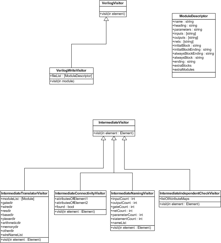
Semantical CorrectnessThe next phase in ensuring correctness will be to check the semantics of the input circuit. For this purpose we will use the Verilog testbenches. Since Verilog testbenches are obviously unable to test a Logisim circuit, the Logisim circuit first needs to be translated into Verilog. Therefore we will convert the Logisim tree structure into a tree structure more fit to represent a Verilog module. This tree structure will then be converted into Verilog code. When this is done, the testbenches will be allowed to run and a semantical report will be produced.
After The First Semester: What I've done up until now
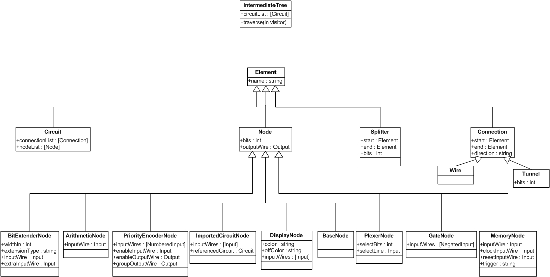
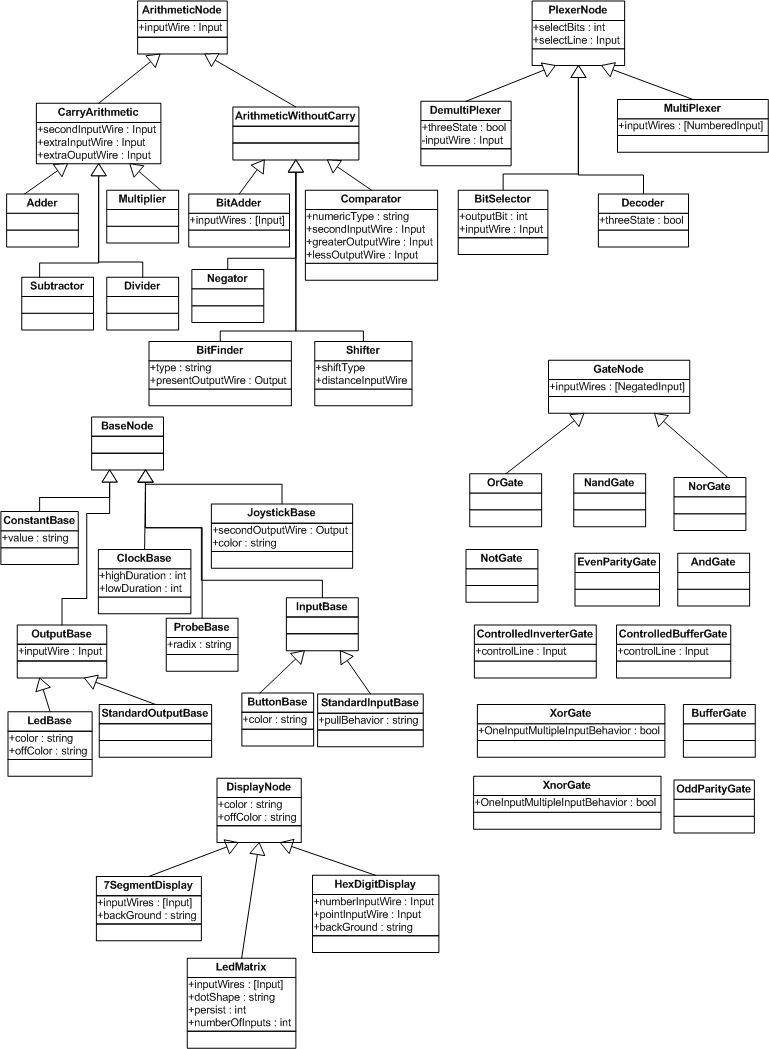
The Intermediate TreeIn the first semester I worked on my intermediate tree for the AND, OR and NOT gates. This tree is structured as followed:
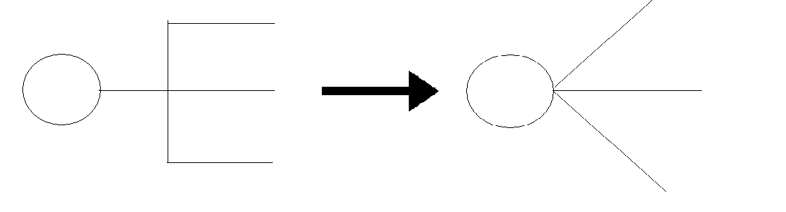
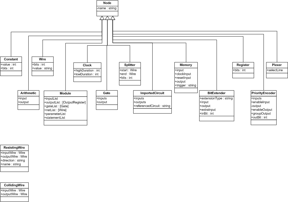
I also wrote a couple of tests, to see if my implementation really works. How to deal with the wires?The main problem with the wires: the angles. We need to translate these angles to straight lines:
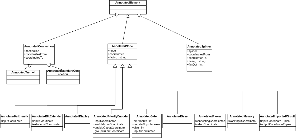
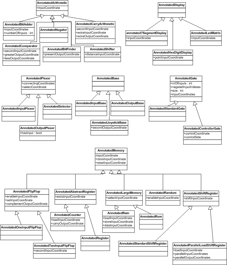
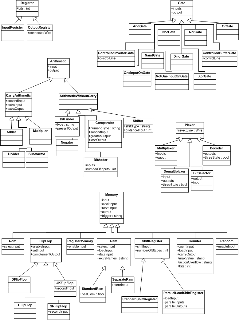
In the logisim xml file, we will see (in the case of the image) 6lines. These six lines will be represented in the intermediate tree by three wires. Class Diagrams
|
| Maintained by Naomi Christis. | Last Modified: 2011/07/07 20:15:09. |