Next: 10. CONCLUSION
Up: 9. APPLICATIONS
Previous: 9.4 Simulation of Software
Contents
Index
Shah Asaduzzaman and Zaki Hasnain Patel have built a TCP model for
SVM. This model simulates communication via the TCP network protocol.
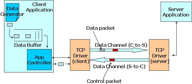
Figure 9.3:
The TCP system
|
|
The communication process of the system is shown in Figure
9.3. There are 6 parts in the system:
- The client application generates data with a data
generator. The data enter a buffer (FIFO queue). They are sent by
the application controller one by one. The client application also
listens to the data coming from the TCP driver.
- The TCP driver on the client side accepts data packets from
the application controller. It sends messages via a network. It
has no buffer. The messages must be sent immediately. It also
listens to the incoming data channel.
- The data channel transfers data packets from the client side
to the server side.
- The TCP driver on the server side accepts data from the data
channel from the client side to the server side. It sends control
information to the outgoing data channel.
- The server application computes with the received data
packets. It generates control packets. Because the control
packets are generated one at a time, buffer is not necessary for
the server. The generated control packets are sent to the TCP
driver on the server side.
- The data channel transfers control packets from the server
side to the client side. Those packets are received by the client
TCP driver.
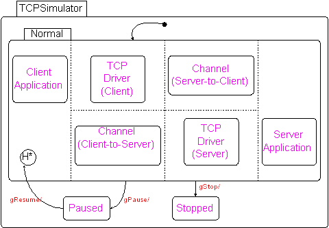
Figure 9.4:
Overview of the TCP simulator
|
|
Each part of the system is modeled with a DCharts orthogonal
component. The whole system is a combination of those orthogonal
components by means of importation (Figure 9.4).
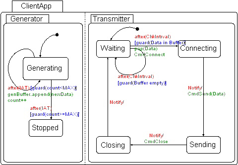
Figure 9.5:
The submodel of the client application
|
|
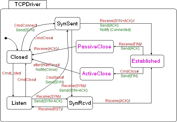
Figure 9.6:
The submodel of the TCP driver (for both client side and server side)
|
|
Figure 9.7:
The ActiveClose state of the TCP driver
|
|
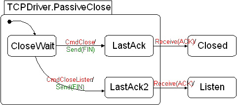
Figure 9.8:
The PassiveClose state of the TCP driver
|
|
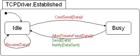
Figure 9.9:
The Established state of the TCP driver
|
|
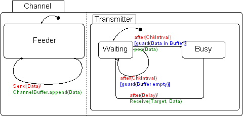
Figure 9.10:
The submodel of the communication channel
|
|
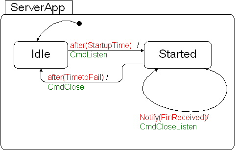
Figure 9.11:
The submodel of the server application
|
|
The 6 parts of the system is modeled with submodels imported into the
total system:
- The client application is modeled in submodel ClientApp
(Figure 9.5).
- The TCP driver is modeled in submodel TCPDriver. It is
for both the client side and the server side, because the API of
the TCP protocol on both sides is exactly the same. The ActiveClose, PassiveClose and Established states of
the submodel are abstracted. Figures
9.7,
9.8 and
9.9 show the internal
structure of those states, respectively.
- The data channels are modeled in submodel Channel
(Figure 9.10). Both channels in the system
are implemented with the same submodel.
- The server application is modeled in submodel ServerApp
(Figure 9.11).
Figure 9.12:
The virtual-time version of the communication channel
|
|
The channel in Figure 9.10 uses the  special event to simulate delay in the network and the time interval
between two subsequent inquiries to the buffer. As a result, this
model is a real-time model. To convert it into a virtual-time model,
Shah Asaduzzaman and Zaki Hasnain Patel have provided another version
of the channel submodel Channel2 (Figure
9.12). The clock component is imported as a
top-level orthogonal component in the system. The new data channel
schedules events by sending the Schedule event to the clock
component. When the virtual time becomes equal to the scheduled time,
the clock component sends back a SchedulerNotify event. (The
schedule event and the notify event discussed in section
9.2 are renamed to Schedule and SchedulerNotify, respectively.)
special event to simulate delay in the network and the time interval
between two subsequent inquiries to the buffer. As a result, this
model is a real-time model. To convert it into a virtual-time model,
Shah Asaduzzaman and Zaki Hasnain Patel have provided another version
of the channel submodel Channel2 (Figure
9.12). The clock component is imported as a
top-level orthogonal component in the system. The new data channel
schedules events by sending the Schedule event to the clock
component. When the virtual time becomes equal to the scheduled time,
the clock component sends back a SchedulerNotify event. (The
schedule event and the notify event discussed in section
9.2 are renamed to Schedule and SchedulerNotify, respectively.)
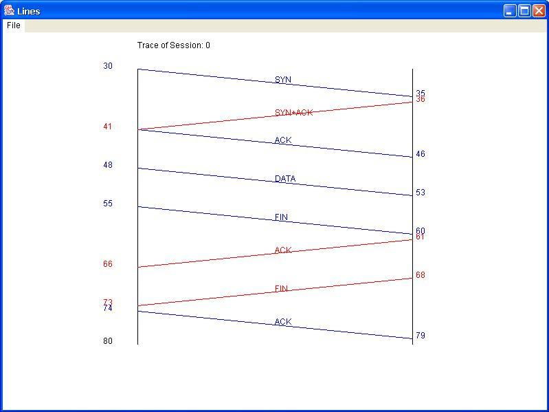
Figure 9.13:
The plot of the simulation result of the TCP model
|
|
The results of the simulation are gathered and plotted in Figure
9.13. For more information about the TCP model,
the readers are referred to Shah Asaduzzaman's on-line report for the
Modeling and Simulation course at McGill University:
Next: 10. CONCLUSION
Up: 9. APPLICATIONS
Previous: 9.4 Simulation of Software
Contents
Index
Thomas Huining Feng
2004-04-28