Default states define the states where a model starts running,
or which substates are the actual destination of a transition. Final states define where a simulation or execution of the model
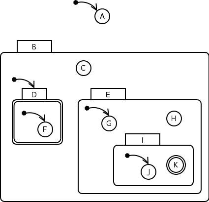
terminates. In the graphical representation of a model, a default
state is drawn as a circle with a black dot pointing to it. A final
state is a state with a double-line border. An example of default
states and final states is given by Figure
![[*]](#fig:defaultfinalsample.png) . In this example, states A,
B.D, B.D.F, B.E.G and B.E.I.J are default
states. States B.D and B.E.I.K are final states.
. In this example, states A,
B.D, B.D.F, B.E.G and B.E.I.J are default
states. States B.D and B.E.I.K are final states.
In this example, B.D is a non-leaf state. Assigning the final property to a non-leaf state is equivalent to making all its substates final. When a transition is fired with a non-leaf final state as its destination, the model will be changed to the leaf substate(s) of the destination state. Those leaf substate(s) (may be more than one because of orthogonal components in the destination state) are all final. The simulation or execution stops after the enter actions of those states are executed. If the destination state or any of its substates is an importation state, the submodel must be imported and all its states become final states. Enter actions in the submodel are also executed. If a finalizer is defined for a model (discussed in section 4.3.4), the finalizer is executed as the last step before the simulation or execution halts. Note that all the above operations are triggered by a single transition. It is illegal to transition out of a final state, whether its final property is assigned by the designer or inherited from its superstates.

|
It is important that there must be default states among all the children of a composite state or an orthogonal component. Orthogonal components are default in their nature, so a composite state that contains orthogonal components need not explicitly specify default substates. For the example in Figure 4.6, all the three orthogonal components of state A are default. Besides this, states A.B.E, A.C.H, A.D.J and A.D.J.K are also default states. State A is a final state, and hence all its substates, including the three orthogonal components in it, are final states. Besides these, state A.D.J.L is a final state explicitly specified by the designer.
AToM![]() uses a different color to represent default states. The
current version of AToM
uses a different color to represent default states. The
current version of AToM![]() does not support the specification of
final states.
does not support the specification of
final states.