In numerical
simulation, when the deceleration of the cam causes the rod to disconnect,
it may make contact the following simulation step. This is shown graphically
in Fig. 16.
In the right-hand figure, the
negative plane of the ![]() axis results in a non-elastic
collision and sets
axis results in a non-elastic
collision and sets ![]() . Mode
. Mode ![]() (where the rod is connected) is
operative on the
(where the rod is connected) is
operative on the ![]() axis as long as
axis as long as
![]() is positive or
0. When
is positive or
0. When ![]() becomes negative, the system switches to mode
becomes negative, the system switches to mode ![]() (where the rod is moving freely). For certain parameter values this moves the
system in the plane where a non-elastic collision occurs, and the system
moves back to the
(where the rod is moving freely). For certain parameter values this moves the
system in the plane where a non-elastic collision occurs, and the system
moves back to the
![]() axis, with
axis, with ![]() . This
chattering behavior is due to the numerical time step and for
. This
chattering behavior is due to the numerical time step and for
![]() the system would remain at (0,0). In Fig. 22 this corresponds
to movement along the sliding surface,
the system would remain at (0,0). In Fig. 22 this corresponds
to movement along the sliding surface, ![]() ,
which is the continuous curve
that represents the movement of the cam in phase space.
This illustrates the
operation of the sliding mode algorithm
on this system, and shows
that the non-elastic collision in simulation results in
,
which is the continuous curve
that represents the movement of the cam in phase space.
This illustrates the
operation of the sliding mode algorithm
on this system, and shows
that the non-elastic collision in simulation results in
![]() for mode
for mode ![]() ,
where the rod and cam are disconnected. In mode
,
where the rod and cam are disconnected. In mode ![]() ,
the rod and cam are connected, and
,
the rod and cam are connected, and ![]() also.
Therefore, the system slides on the switching surface and there is no
error due to chattering.
This conforms with physical behavior
due to unmodeled higher order physical
phenomena such as adhesive forces between the rod and cam, which
results in the rod and cam moving with the same velocity.
also.
Therefore, the system slides on the switching surface and there is no
error due to chattering.
This conforms with physical behavior
due to unmodeled higher order physical
phenomena such as adhesive forces between the rod and cam, which
results in the rod and cam moving with the same velocity.
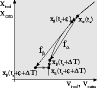
Figure 22: Sliding mode simulation for the cam-follower system.
Simulation results with a fixed step Euler are shown on the left in Fig. 23. The chatter error can be reduced by using a smaller step size, but a variable step size integration method cannot be applied since it would reduce the step size to its lower bound for a large number of simulation steps. Sliding mode simulation, shown on the right in Fig. 23, has no error because it accounts for the discontinuous jump in rod velocity. The results show that sliding mode simulation correctly turns off when system behavior moves away from the switching surface.
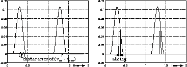
Figure 23: Sliding mode simulation during an interval of time.